Defensive Barrier Engineering & Deployment Guide: Manufacturing to Field Application
In modern protective engineering, the defensive barrier—a composite structure composed of welded wire mesh and high-tensile geotextile—serves as a primary physical mitigation solution for military fortification, perimeter security, and flood defense operations. Compared to conventional sandbag installations, this modular, accordion-style design increases deployment speeds by approximately tenfold while drastically improving structural resistance to blast overpressure, ballistic fragmentation, and hydrodynamic scour.
Manufacturing Standards & Quality Assurance
Producing a mission-critical protective unit requires precise metallurgical control and fabrication tolerance. Any sub-par weld or defective anti-corrosion coating risks structural rupture when filled under high kinetic loads with dense gravel or aggregate.
Raw Material Technical Specifications
-
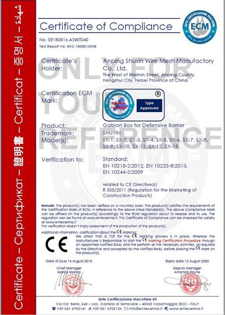
Wire Mesh Core: Low-carbon structural steel wire manufactured in strict compliance with ASTM A641/A641M, engineered to an ultimate tensile strength of $450 text{--} 550text{ MPa}$.
-
Protective Coatings: Hot-Dip Galvanized (HDG) per ISO 1461 with minimum coating density of $ge 260text{ g/m}^2$, or 95% Zn / 5% Al Galfan alloy coatings. Assemblies undergo standard ASTM B117 salt-spray testing exceeding 1,000 continuous hours to survive high-salinity marine environments.
-
Geotextile Liner: Non-woven needle-punched polypropylene (PP) staple fibers ranging from $250 text{--} 400text{ g/m}^2$. The fabric incorporates Hindered Amine Light Stabilizers (HALS) to preserve at least 70% of tensile integrity after 500 hours of ASTM G154 accelerated UV exposure.
Manufacturing Stages
-
Automated Multi-Point Resistance Welding: High-grade wire rods are precision-straightened, cut to length, and processed through multi-electrode automated welders. Consistent current and pneumatic pressure ensure aperture dimensional tolerances within $pm 2.0text{ mm}$.
-
Helical Hinge Fabrication & Jointing: High-tensile spring steel is coiled into tight-pitch spiral binders. Panels are placed in alignment jigs where operators lace helical joints across adjacent segments, forming the collapsible cell lattice.
-
Internal Fabric Insertion & Stitching: Precision-cut geotextile sheets line the steel matrix and are anchored with UV-stabilized heavy-duty nylon threading to prevent slump, detachment, or tears during rapid mechanized filling.
Production QA Testing Protocols
-
Weld Shear Strength: Randomly sampled grid intersections must exhibit shear strength exceeding 75% of the base wire's minimum specified tensile strength. Failure under hydraulic pull-testing must occur in the parent metal, not the weld zone.
-
Puncture & Tear Resistance: Geotextile specimens undergo standard California Bearing Ratio (CBR) push-through tests and falling-cone drop-puncture evaluations to confirm structural integrity against jagged rip-rap and crushed stone backfill.
Field Deployment & Operational Protocols
Maximizing kinetic energy dissipation requires standardized deployment practices, combining mechanical handling with disciplined site preparation.
Step-by-Step Installation Procedure
-
Subgrade Preparation: Clear obstructions, boulders, and standing surface water along the trace. Grade the alignment within a 5° slope tolerance to avoid lateral shear stresses.
-
Cell Expansion & Pin Locking: Pull the collapsed module outward along the trace to its full rectangular profile. Thread heavy-duty steel connecting pins through adjacent joints to lock adjoining cells into a single rigid wall.
-
Incremental Backfill & Consolidation:
-
Utilize a front-end loader, skid-steer, or hydraulic excavator bucket to deposit fill material (bank-run gravel, dry sand, or native soil).
-
Deposit material uniformly along the axis in lifts of 300–400 mm rather than loading single cells to maximum capacity, preventing panel deflection or hinge binding.
-
Mechanically vibrate or hand-tamp successive lifts to eliminate internal air voids.
Field Use Cases
| Operational Context |
Typical Wall Profile |
Primary Mitigation Mechanism |
Maintenance & Inspection Focus |
| Forward Operating Base (FOB) Perimeter |
Two-tier stack (2 m base, 1 m cap) + concertina wire |
Massive ballast mass absorbs blast waves; steel mesh confines fragmentation |
Inspect lower cells for fabric abrasion or loose fill leakage |
| Flash Flood Mitigation & Diversion |
Single-tier linear run + downstream rock rip-rap counterweight |
Hydrostatic deadweight offsets shear force; micro-porous geotextile relieves pore-water pressure |
Monitor seams for scour and erosion; place impervious geomembranes upstream if needed |
| Ammunition & Fuel Revetment |
Horseshoe-shaped cellular bund with lightweight overhead cover |
Attenuates primary blast overpressure; limits sympathetic detonation propagation |
Check connector pins for shear distortion and lateral displacement |
Lifecycle Maintenance & Performance Assessment
An objective assessment of structural boundaries ensures effective logistics planning, maintenance scheduling, and lifecycle budgeting.
Advantages & Operational Limitations
-
Key Strengths:
-
Rapid Deployment: A four-person crew with one front-end loader can erect and fill a 10-meter protective wall within 20 minutes.
-
Material Flexibility: Compatible with virtually any localized backfill—including sand, river gravel, and common excavation tailings.
-
Operational Limitations:
-
Broad Footprint: Gravity-retaining architecture requires a wide operational base, limiting deployment in constrained urban alleys or indoor structures.
-
Demobilization Costs: Extended deployments cause internal backfill to compact and consolidate, necessitating destructive wire-cutting for extraction and reducing salvage value.
Scheduled Maintenance Protocol
-
UV Degradation Audits: Polypropylene fabric remains the component most susceptible to sun exposure. If surfaces display visible chalking, fraying, or fiber embrittlement, apply a pneumatically sprayed shotcrete mortar topcoat or install auxiliary secondary mesh panels.
-
Deflection & Bulge Tolerances: Survey structural alignments biannually or following extreme weather events. If outward face displacement exceeds 8% of original cell width, reinforce the section with raked steel deadman shores or construct an exterior buttress tier.
Frequently Asked Questions (FAQ)
Q: How does a defensive barrier absorb incoming ballistic rounds or indirect shrapnel?
A: The system pairs mechanical mass dissipation with structural wire-confinement dynamics. As projectiles penetrate the fill, high-friction particle-to-particle contact strips kinetic energy and destabilizes the round's trajectory. Meanwhile, the exterior high-tensile wire mesh absorbs lateral kinetic shockwaves, preventing catastrophic aggregate displacement.
Q: Can fine-grain beach sand be used if aggregate or crushed rock is unavailable?
A: Yes, provided the geotextile liner's Apparent Opening Size (AOS) is finer than the median grain size of the sand to prevent fine-particle leaching. When deploying pure sand in high-precipitation environments, cover the top of the barrier with a waterproof geomembrane to prevent moisture saturation and internal hydraulic slumping.
Q: What is the service life of galvanized mesh units installed directly on damp ground?
A: Longevity depends on soil resistivity, moisture levels, and acidity. In neutral soils (pH 6–8), a standard Galfan-coated (95% Zn / 5% Al) mesh unit typically provides a service life of 10 to 15 years. For continuous coastal splash zones or acidic peat terrain, specify PVC-extruded or polyolefin-coated wire to prevent corrosion degradation.


 Ihre Nachricht muss zwischen 20 und 3.000 Zeichen enthalten!